Page 28 - RAYCOH_2026ENV3.0_Sensors
P. 28

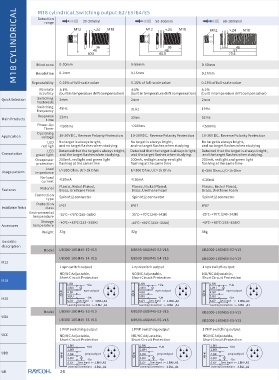
M18 CYLINDRICAL  E8 /E9 dual switch four output modes   1. Switching mode  A2             Target range
                                                                  2EP-IO switching output mode


                           Switch A1 Switch A2 Switch A3Switch A4
                   1.
                   Output 1
                                                                 NO
                   Output 2
                                         Switch A2
                              Switch A1
                                                                 NC
                                                                                 A1
                   Output 1
                   Output 2
                                   hysteresis interval
                                                                  NO
                                                                  NC
                   Output 1
                                                                                 A2
                                                                                               A1
                   Output 2  Switch A1   Switch A2               2.Window        A1           A2
                                                                 3. hysteresis mode  A1        A2
                   4.         Single switching
  Quick Selection
                    Output 1                   Target range        NO mode
                    Output 2
  Main Products                                                    NC mode
                                                                                  A2           A1
   Application                                                   4. Reflection mode
                                                                                                 A1  A2
                                                                  NO
   Connotation    Analog output mode                                                                 Reflector plate
                                                                  NC
                                A1       A2                                                     A2    A1
   Usage pattern   up mode
                   A1<A2:
                                             Target range
   Features
                 down mode
  Installation Notes  A2<A1:
                                A2       A1
   Accessores


   Unstable
   description

   M12

                  Output mode of analog+switch
   M18


   M30
                        Up mode
                        A1<A2:                    Target range
                                   A1       A2
   UDA            4.BK
                    descent mode
                      A2<A1:
   UCC
                                   A2       A1
                        Windows mode1, NO
   UDB
                        A1<A2:
                                    A1        A2
                  2.WH
   UR                   Windows mode2, NC
                        A2<A1:

   Special Series                   A2        A1

   Square Series


  Wireless Series


   UGT                     26
   23   24   25   26   27   28   29   30   31   32   33