
Page 22 - RAYCOH_2026ENV3.0_Sensors
P. 22
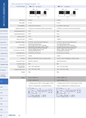
M12 CYLINDRICAL  down mode  A1   A2  Target range         Ultrasonic sensor with switch output, the corresponding two


                  Analog output mode
                                                                      Teach-in function

                   up mode
                   A1<A2:
                                                                  Sett switch point

                                                                  switch  points  can  be  set.  The  setting  method  is  to  connect
                                                                  the TEACH-IN learning line to the power supply -UB or +UB
                   A2<A1:
                                                                  respectively, and the connection time is at least three times
                                                                  the LED light indicates whether the sensor detects the target.
                                                                  Set A1 point when the TEACHIN learning line is connected to
                                                                  -UB, and set A2 point when it is connected to +UB.
                UB120           A2       A1                       when  the  indicator  light  flashes.During  the  setting  process,
  Quick Selection
                      Y(mm)                                       The following five different output functions can be selected:
                        75
  Main Products                                                   mode  condition           requirement
                        50
                                                                                   Place the target at the near switch point,connect
                        25
   Application                                                                     the TEACH-IN learning cable to the -UB setting A1
                                                                                   point until it is green and the indicator light blinks
                                                                                   more than 3 times, disconnect it.
                       -25                                                NO
   Connotation                                                                     Place  the  target  at  the  far  switch  point,  connect
                       -50                                                         the TEACH-IN learning cable to the +UB setting A2
                                                                                   point until it is green and the indicator light blinks
                       -75                                                         more than 3 times, disconnect.
   Usage pattern
                          0  25 50  75  100 125 150 175 200         Windows mode
                                                 X(mm)                             Place the target at the near switch point, connect
                                                                                   the TEACH-IN learning cable to the +UB setting A2
   Features                                                                        point until it is green and the indicator light blinks
                                                                                   more than 3 times, disconnect.
                        flat10×10mm         round rod  Ø  8mm             NC
  Installation Notes                                                               Place  the  target  at  the  far  switch  point,  connect
                                                                                   the TEACH-IN learning cable to the -UB setting A1
                                                                                   point until it is green and the indicator light blinks
                                                                                   more than 3 times, disconnect.
   Accessores   UB200
                                                                                   Place  the  target  at  the  near  switch  point  and
                                                                                   connect  the  TEACH-IN  learning  cable  to  the  +UB
   Unstable            Y(mm)                                                       setting  A2  point  until  the  green  indicator  blinks
   description                                                                     more than 3 times, disconnect.
                       150
                                                                          NO
                                                                                   Disconnect by covering the sensor with your hand
   M12                 100                                                         or  removing  all  objects  within  the  sensor's
                                                                                   detection  range  until  the  green  indicator  light
                                                                    Switch Mode
                       50                                                          blinks  more  than  3  times.  Connect  the  TEACH-IN
   M18                                                                             learning cable to the -UB to set point A1.
                       -50                                                         Place the target at the near switch point, connect
                                                                                   the TEACH-IN learning cable to the -UB setting A1
   M30                -100                                                         point until the green indicator blinks more than 3
                                                                                   times, disconnect.
                      -150                                                NC
                          0  50 100 150 200 250 300 350 400                        Disconnect  the  sensor  by  covering  it  with  your
   UDA                                                                             hand  or  removing  all  objects  within  the  sensor's
                                                X(mm)                              detection range until the red indicator light blinks
                                                                                   more  than  3  times.  Connect  the  TEACH-IN
   UCC                                                                             learning cable to +UB to set point A2.
                        flat10×10mm         round rod  Ø  8mm                      Cover  the  sensor  with  your  hand  or  remove  all
                                                                    Object presence   A1 until the red indicator light blinks more than 3
   UDB                                                                             objects  within  the  sensor's  detection  range.  Set
                                                                                   TEACH-IN Learning Cable Connection-UB to point
                  Teach-in function                                   detection model  times  to  disconnect.  Set  point  A2  by  connecting
   UR                                                                              the TEACH-IN learning cable to the +UB until the
                                                                                   red  indicator  light  blinks  more  than  3  times  to
                  Sensors of different models or the same model can                 disconnect.
   Special Series  realize asynchronous function or synchronous function,
                which needs to be realized by synchronous controller.
                                                                  Factory settings
   Square Series                                                  A1 : Blind zone (minimum working range)
                                                                  A2 : Maximum range
  Wireless Series


   UGT                     20